Modular Bio-Inspired Robot
overview
the challenge
the result
TEAM
Shafae Ali
year
2020
Research
Initial Enquiry
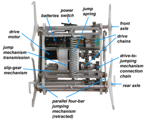
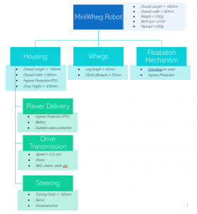
To better understand the task, I went about understanding the basic component configuration of the MiniWheg, starting with the CWRU paper and videos.
“The overall design goals for the Mini-Whegs robot series are functionality, simplicity, compactness, and durability.”
Identified Limitations
– Difficulty moving over surfaces where wheel-legs can penetrate and catch, e.g. slatted surface, cables, brushes, etc.
– Delrin wheel-legs can causes slipping on hard or polished surface.
– Current chassis is not waterproof meaning that usability in outdoor conditions is limited.
– FDM or injection molded chassis construction will make the project more accessible and easier to construct.
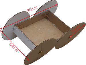
Low-fideltity Prototyping
I used cardboard prototyping to gain a better understanding of spatial features and interrogate the specification. It provided clarity in potential component layout and modifications from the basic configurations.
Ideation
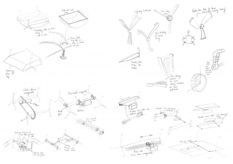
Sketching and Morphological Analysis
Using the moodboard generated and relevant research, I began ideating potential drive mechanisms, steering methods and features to enhance performance. I used a morphological analysis to build a variety of designs and variants.
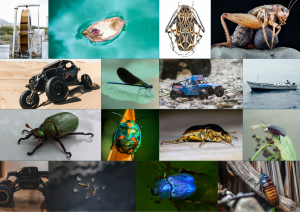
Insect Floatation Mechanisms
A further inspiration area based on the CWRU cockroach locomotion, was the mechanims for traversing water. Various videos were analysed of cockroaches swimming and the Water Boatman to identify how they float. They retain air inside them, but not all cockroaches are capable of this as it is highly dependent on their specific mass to volume ratio. For the purposes of the MiniWheg robot, an increase in volume would be feasible to achieve the required densiy to achieve buoyancy in water.
Mechanical Analysis Development
Floatation
Using basic density calculations, the robots relative density to water was estimated to determine the feasability of such a feature. The result demonstrates that the limiting factor is volume, and by increasing this, would likely affect whether the specifcations are met. As a result, this feature can be achieved through swappable components – modularity of the robot.
Motor Selection
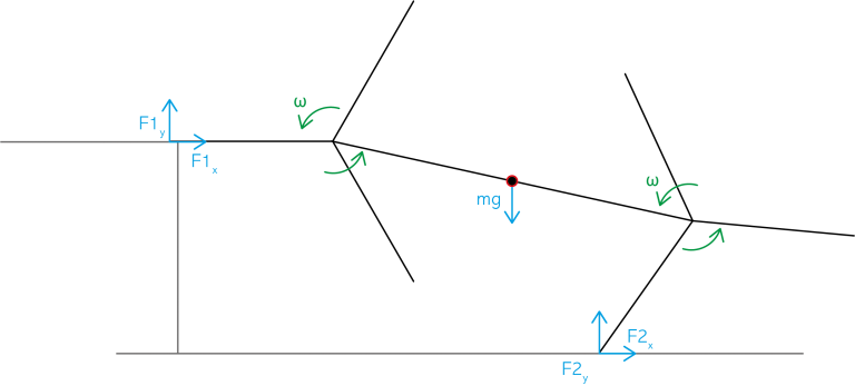
Free-body diagrams were created to represent and understand worst-case load scenarios. A matrix was created to evaluate different motor types using cost, RPM, torque and physical dimensions to inform the decision.
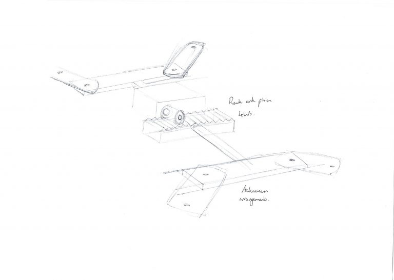
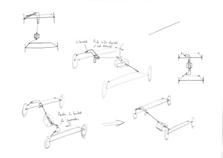
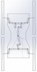
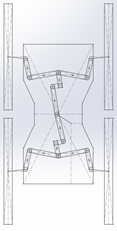
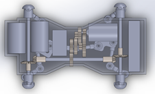
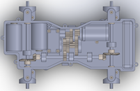
2D Ackermann Model
To achieve 4-wheel steering and avoid skid, an Ackermann model was produced. Steering angles were calculated for a symmetric system. A 2D Solidworks live model was used to test mechanical repsonse of the linkages – this is allowed for a greater number of iterations given it is less intensive to compute than a 3D model. The final design is a bell crank system with modified linkage lengths that requires only 3 unique parts to achieve a tight turning circle as set out by the specfications.
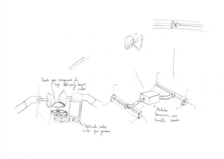
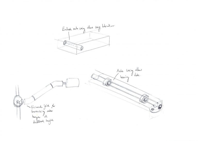
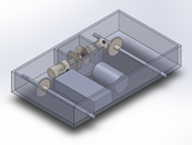
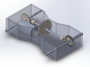
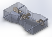
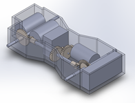
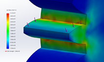
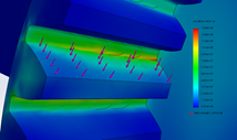
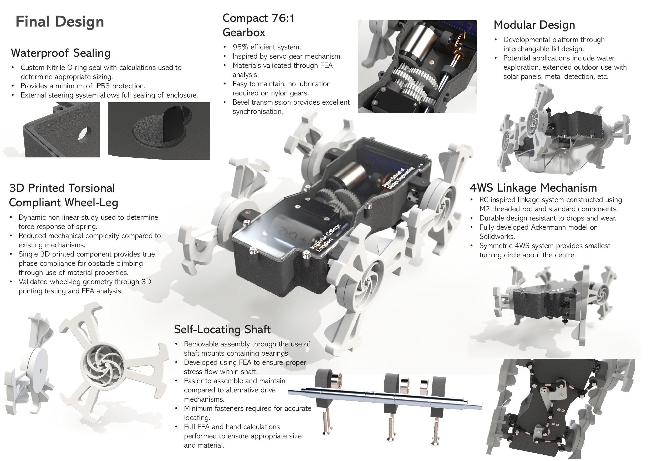
Gearbox Transmission
After multiple iterations, a drive shaft assembly was used as opposed to chain or belt drive. This setup allows for a lightweight and efficient assembly, easy maintainence, accurate synchronisation, unaffected by elongation over time. The gearbox ratio required to increase motor torque was also calculated and a 76.1:1 setup was required to achieve this. The gears were then analysed with maximum tangentual forces applied and FEA analysis completed to determine a suitable material. It was found that Nylon had suitable UTS to be used.
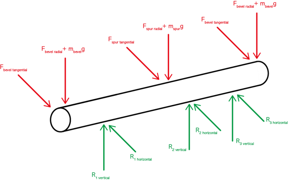
Shaft and Gear Failure Analysis
Free-body Diagram
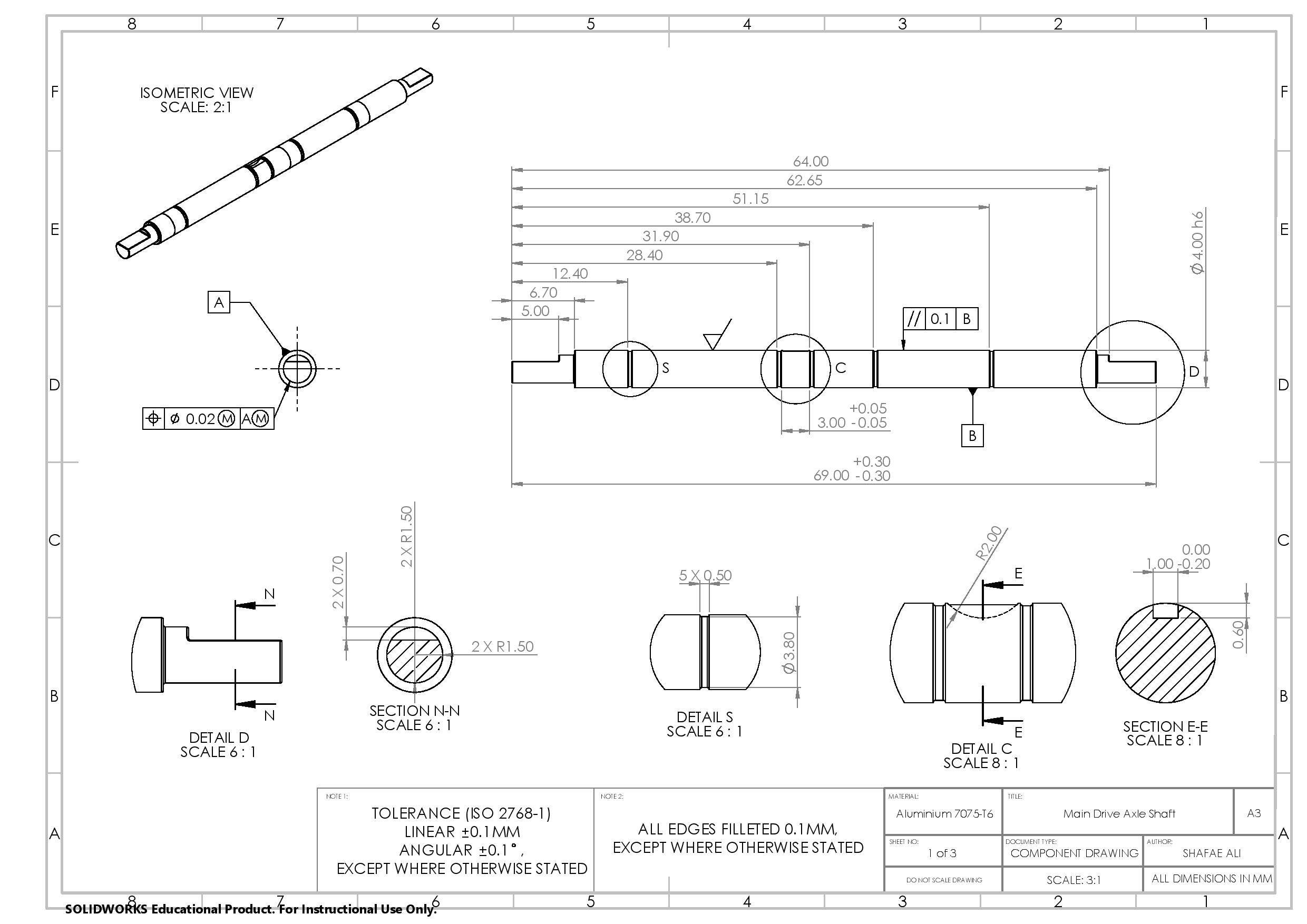
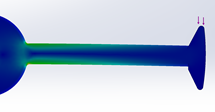
The maximum shear stress acting on the shaft was evaluated to determine appropriate materials and dimensions. A 2mm size was initially chosen to ensure minimum mass was used, whilst also being practial in manufacture. The minimum angular deflection was also calculated, but was found to be excessive. The analysis was repeated for increasing shaft diameters and a 4mm shaft was found to be ideal as it had a deflection less than 0.23. The chosen material was 7075-T6 aluminium as it has a high strength to weight ratio, and also results in a safety factor of 40.
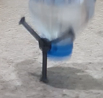
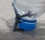
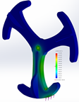
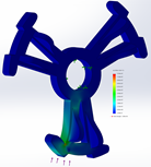
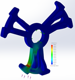
Wheel-leg Drop Test
Slow Motion Footage and FEA Analysis
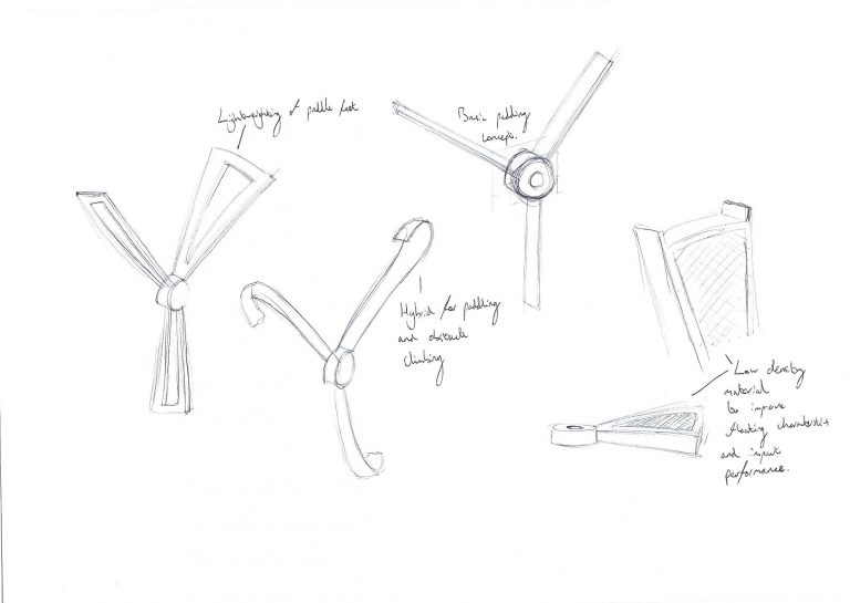
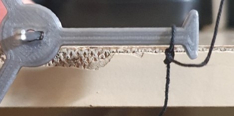
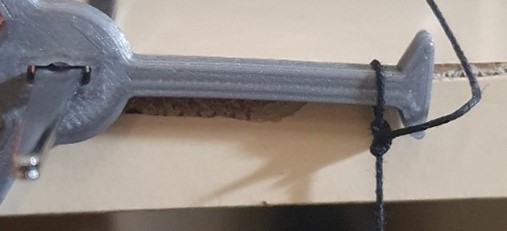
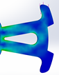
To ensure the wheel-legs met specfication and would not fail under dynamic loads, FEA simulations were completed to inform iterations. To setup the simulation, a real world test was first peformed to estimate deformation time of the material. The mass of the robot falling on to a leg was replicated using a water bottle. Slow-motion footage was then captured and the number of frames between contact with the fround and the leg breaking was analysed. This was found to be 3ms of deformation which informed the force calcualtion that could be used in a static FEA simulation. The wheel-leg was then iterated such that it retains fins and lightweighting for traversing waters, but is also robust enough to climb obstacles. Fillets were added at stress concentrators to reduce stress by 23%.
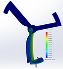
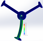
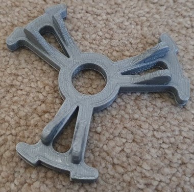
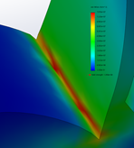
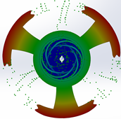
Wheel-leg Phase Mechanism Compliance
FEA and Non-linear Dynamic Analysis
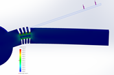
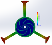
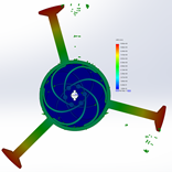
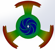
The legs of the wheels are out of phase so that it can replicate cockroach locomotion, however a feature added by CWRU was phase compliance so that when climbing obstacles, the MiniWheg could increase the torque available to it by using two legs to climb rather than one. The existing mechanism was either too large or unreliable, so I decided to explore compliant torsion springs as an alternative. Using basic cut outs at the root of the leg resulted in signifigant stress and did not allow for large amounts of displacement. 3D printing was once again used to inform the FEA simulations. Given that one of my parameters was to optimse the design for 3D printing, I came across a torsioanlly compliant spring that was made as a 3D printing toy. I decided to adapt this and build it into the wheel-leg, using the axle as a fixed point for where force could be applied. A non-linear dynamic analysis was setup to understand the force response of the mechanism and was found that spring fiber thickness could be adapted such that, the spring activates above a certain force thershold. A displacement of 60 degrees was achieved without execssive stress. This solution provides a less mechanically complex way of integrating phase compliance, with the use of a single 3D printed part. To further prove this out, a high quality SLA printer would have to be used to achieve tolerances required for this part.
Hero Page
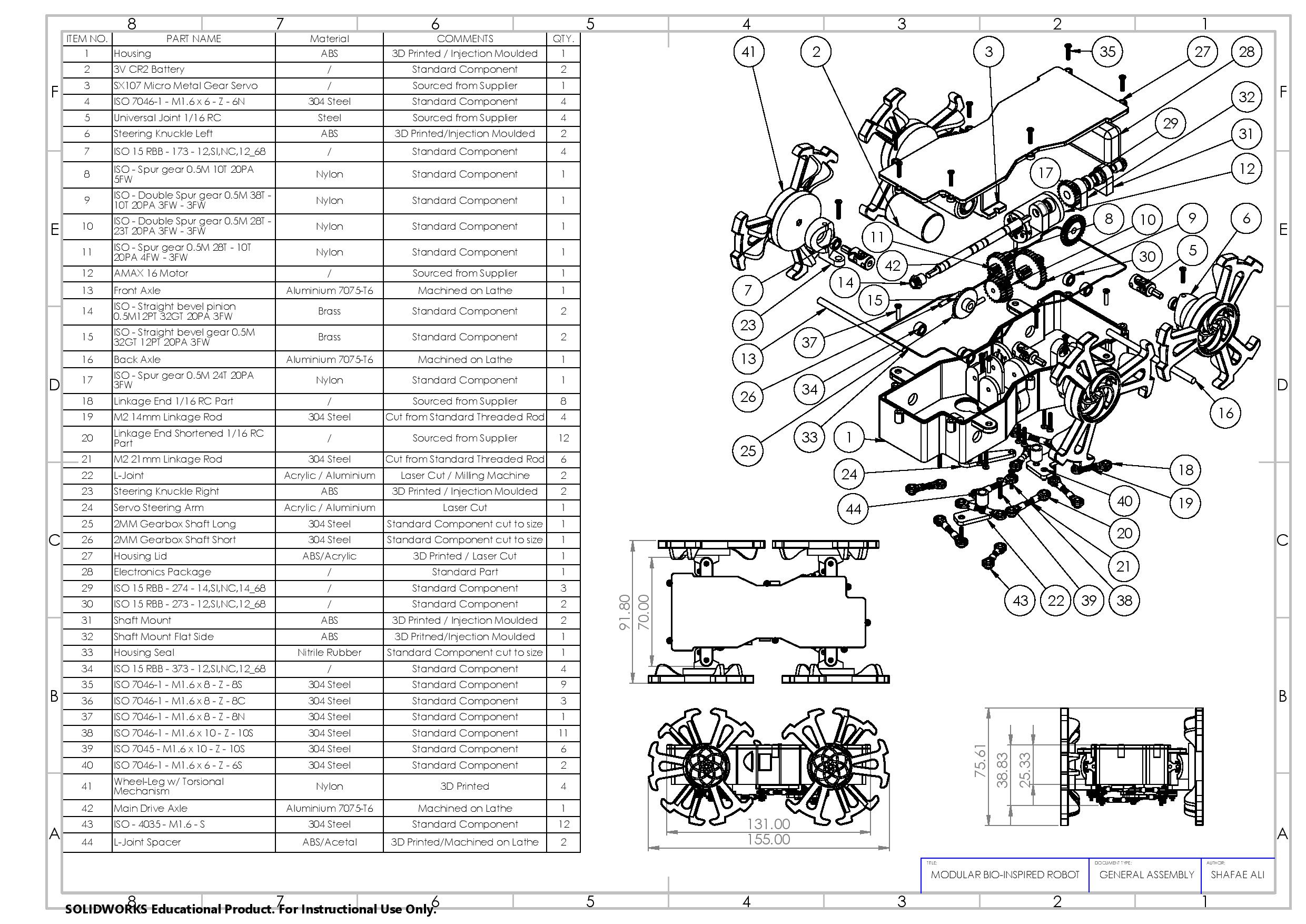
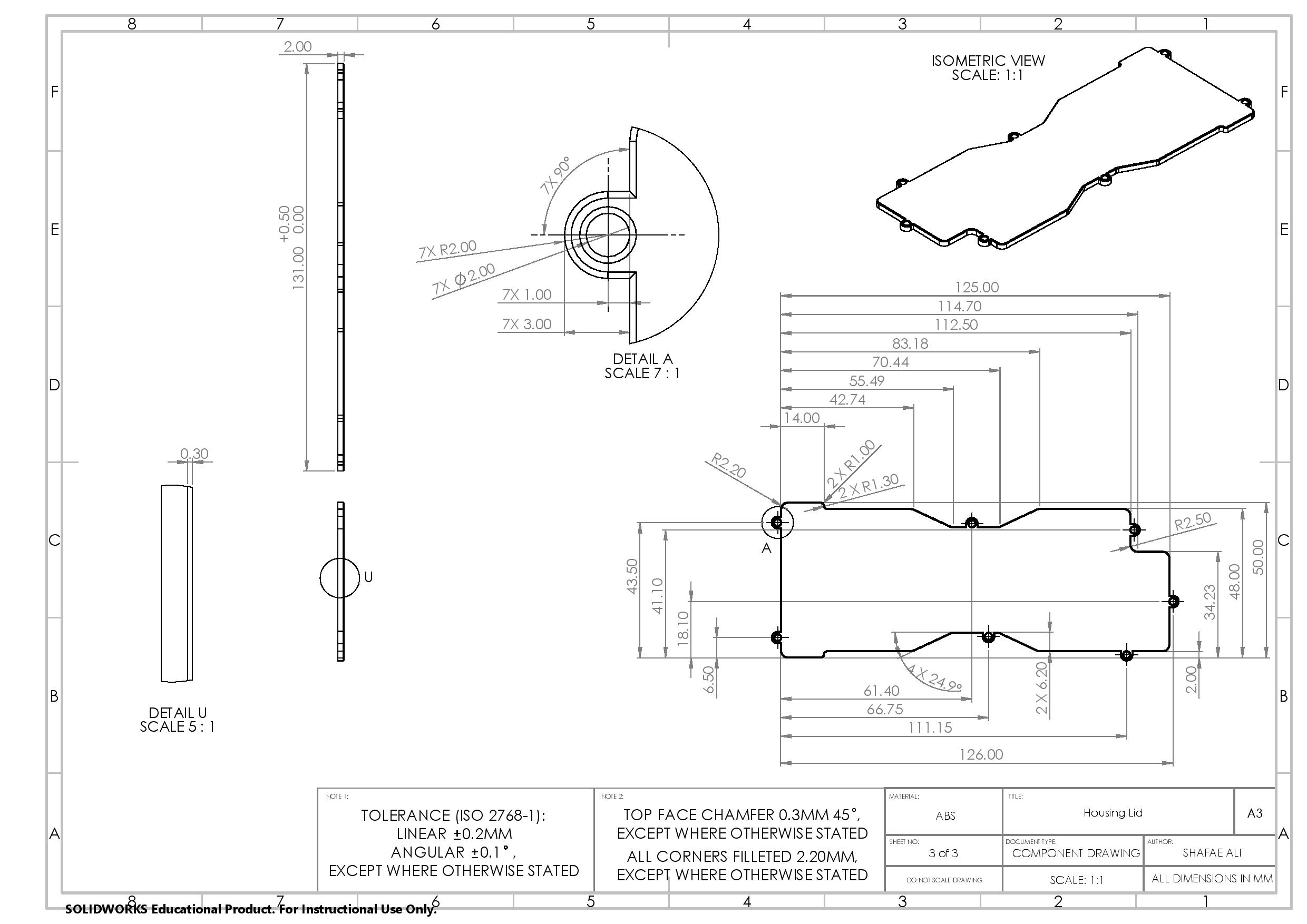
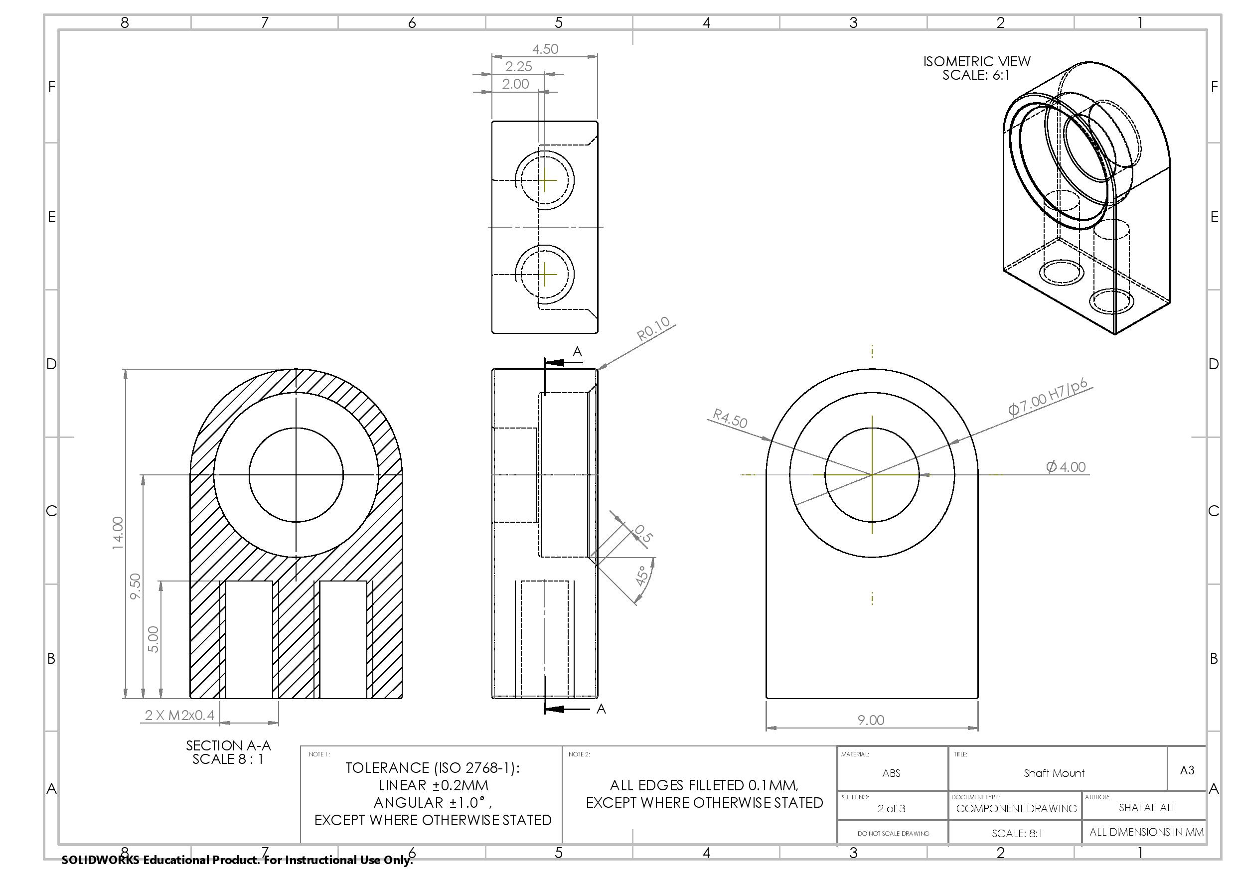
BOM and Technical Drawings